Prioritizing completion speed over quality creates height variations and wavy floor profiles, driving up continuous hidden costs.
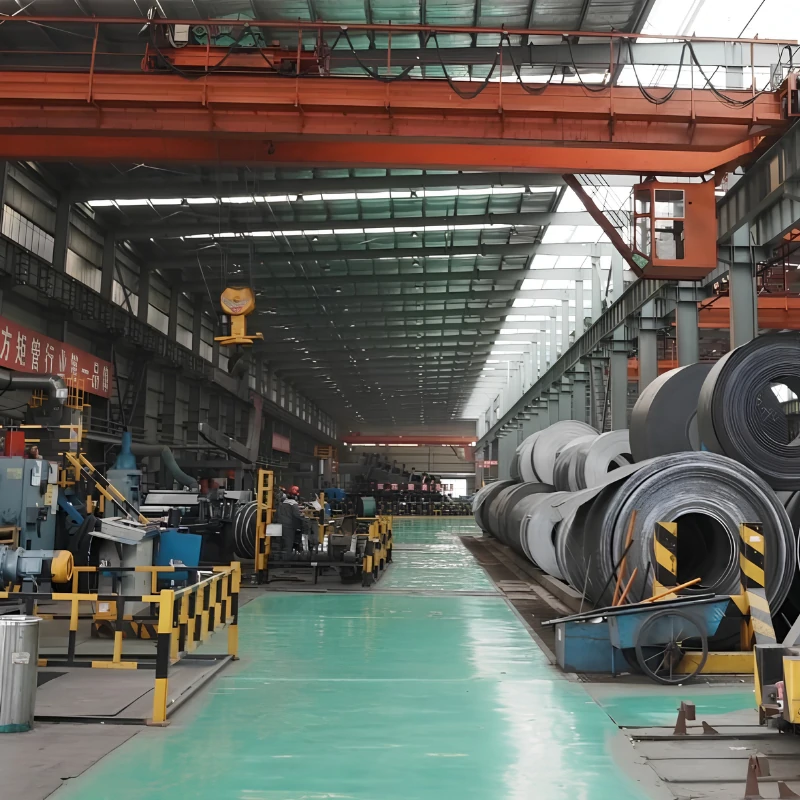
Uneven floors → Eccentric rack loading and reduced load capacity; excessive use of leveling shims makes installation time-consuming and costly; forklifts are forced to slow down, reducing operational efficiency.

Uneven floors distort precision machine tool measurement data, widening machining tolerances; AGV tire wear accelerates, causing maintenance costs to surge.
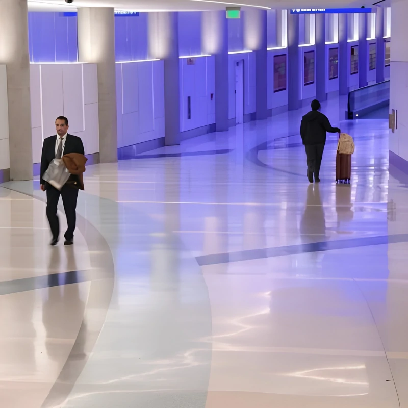
Under lighting, wavy floor profiles cause visual distortion, negatively impacting display aesthetics and customer experience.
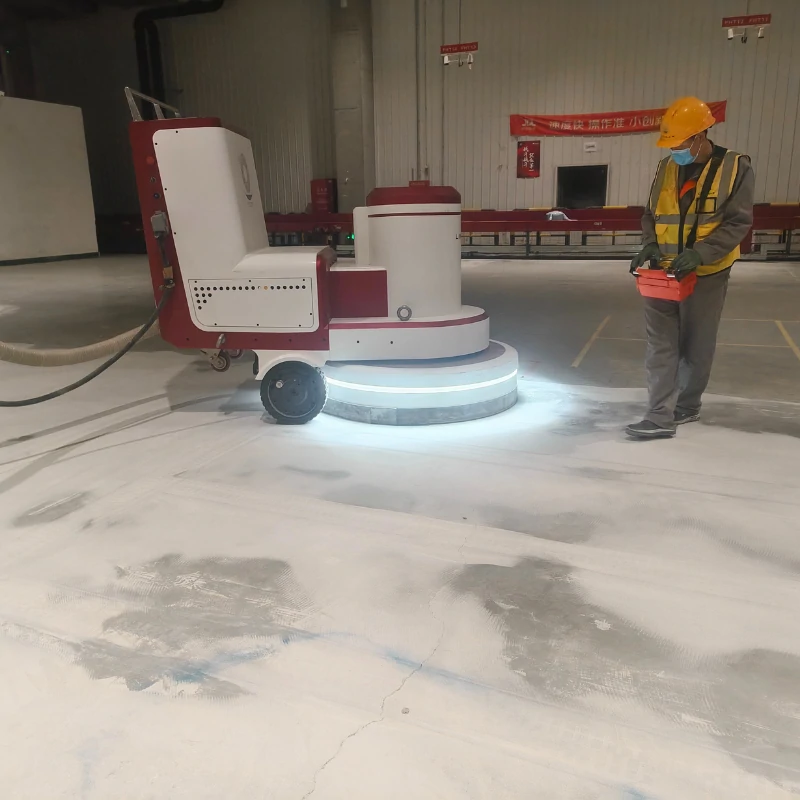
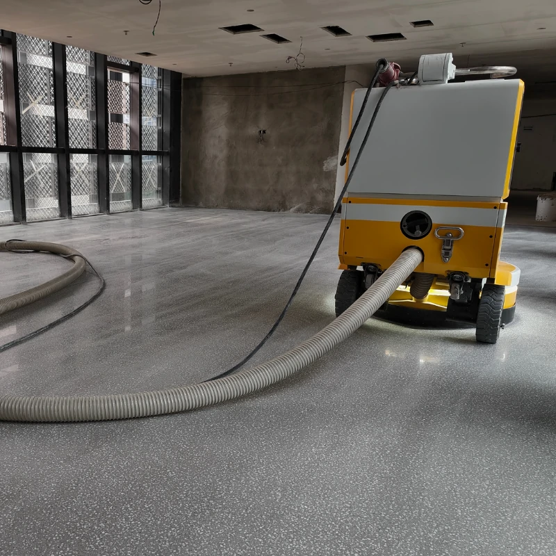
Proprietary high-precision grinding equipment combined with specialized abrasive pairings eliminates height variations and wavy profiles through multi-pass fine grinding.
| FF≥150 | Floor Flatness Index | Tested per ASTM E1155 |
| FL≥100 | Floor Levelness Index | F-Number System |
| 3m Straightedge<1.0mm | Gap between floor and straightedge | Industry Ultra-Flat Grade |
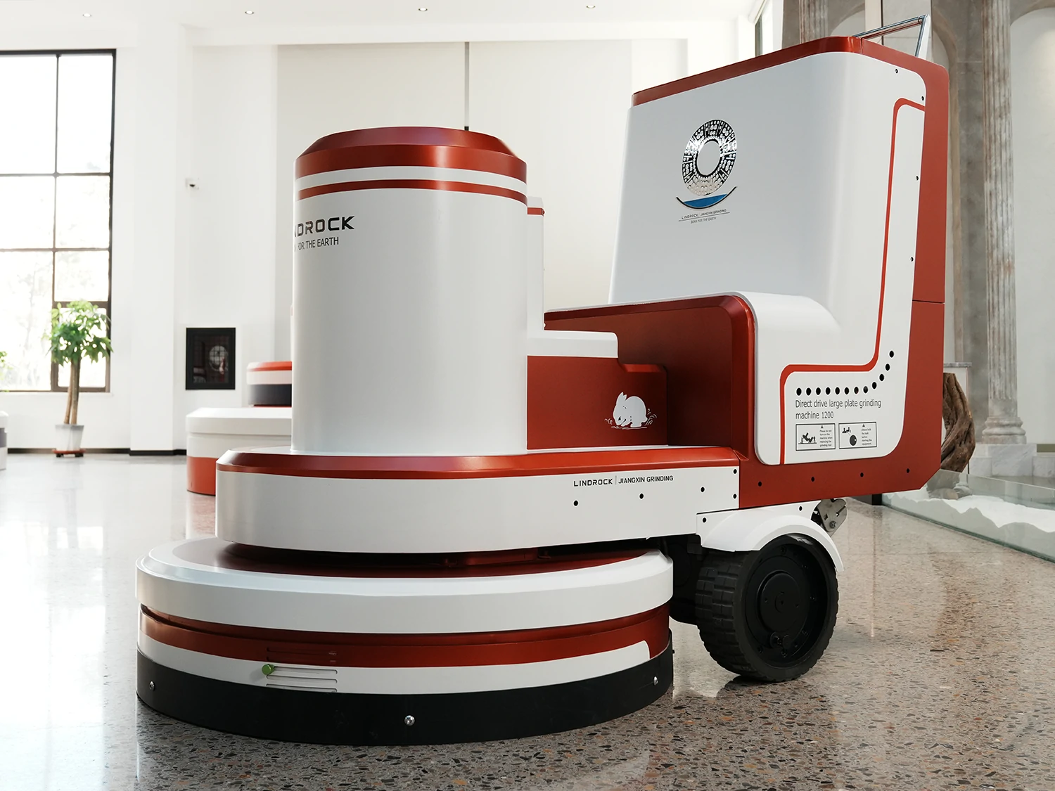
A single grinding pass covers a complete floor unit, leaving a flat surface free of wavy profiles.
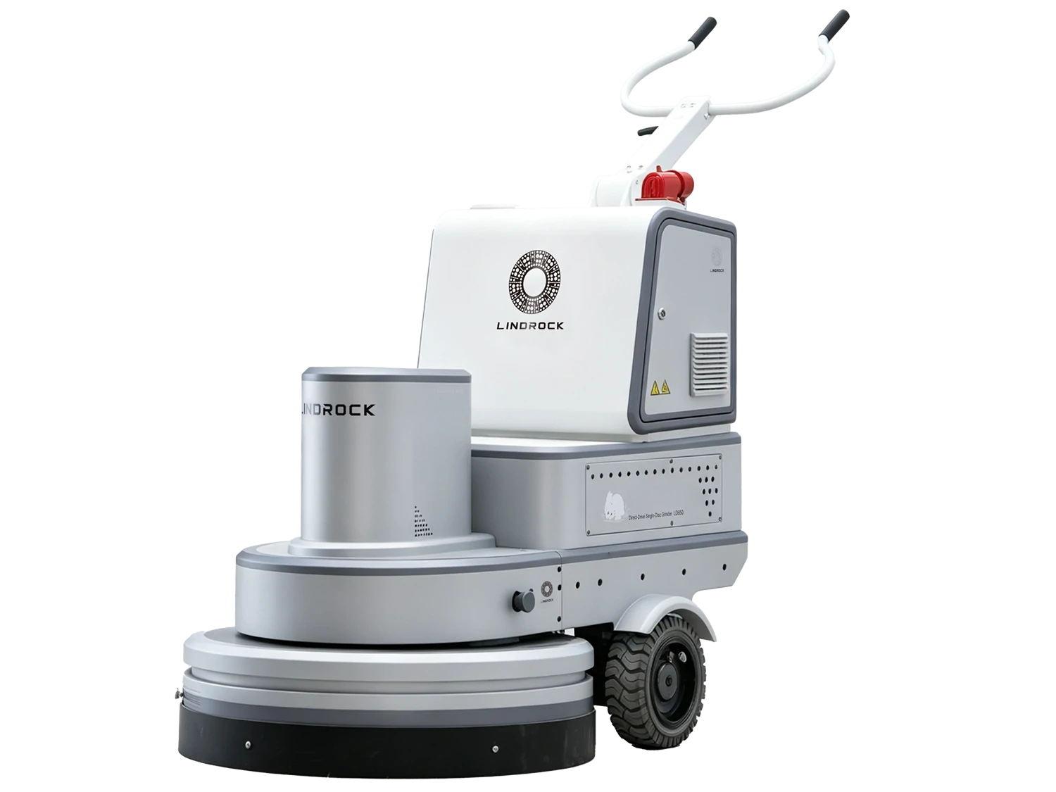
The combined weight and rigid connection of the grinding head concentrate grinding pressure on high spots, cutting peaks first while preserving low points to achieve high-precision leveling.

Effortlessly tackles hard surfaces such as C80 high-strength concrete, maintaining full cutting speed and unyielding pressure.
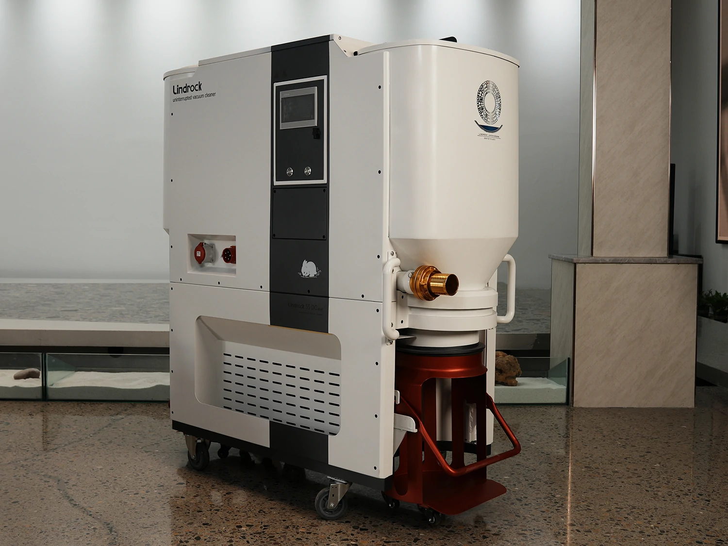
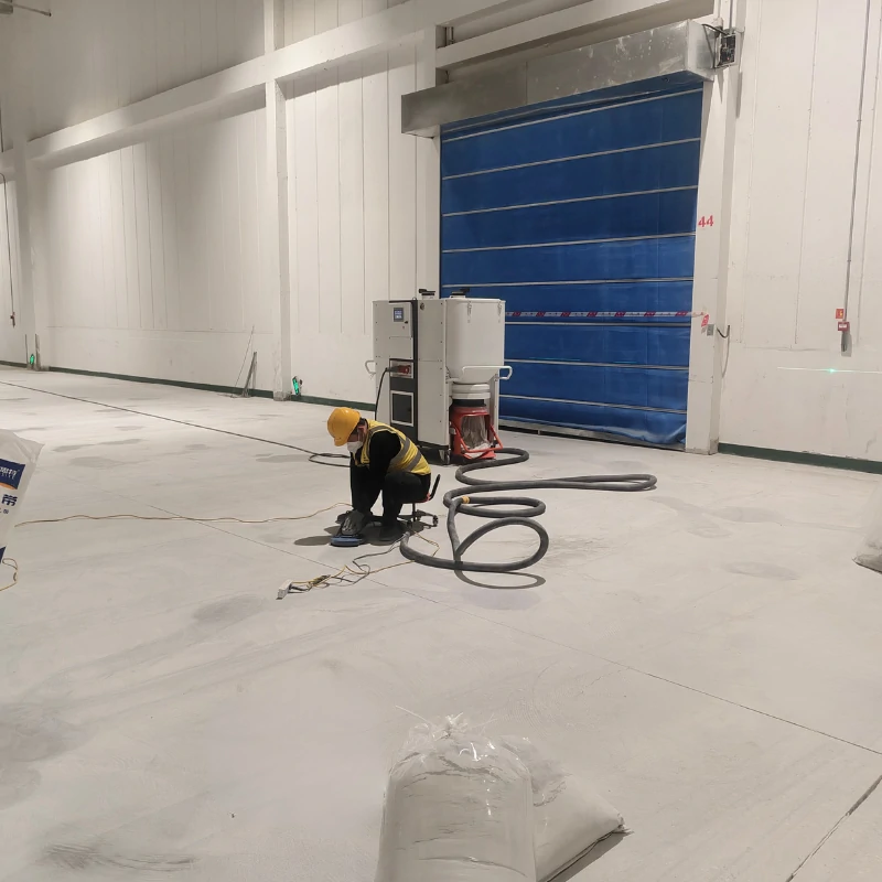
A high-performance dust extraction system dramatically reduces operational dust, optimizing the work environment and protecting worker health; enables cross-trade concurrent construction, shortening business downtime for commercial spaces and reducing operational impact.
From site assessment and solution matching to material selection and custom engineering, every project is handled through a dedicated design process built for demanding environments.
Chip fabs, aerospace assembly, coastal chemical plants, heavy-load port storage, precision equipment manufacturing, high-bay warehouses - anywhere flatness, cleanliness, and durability are critical.
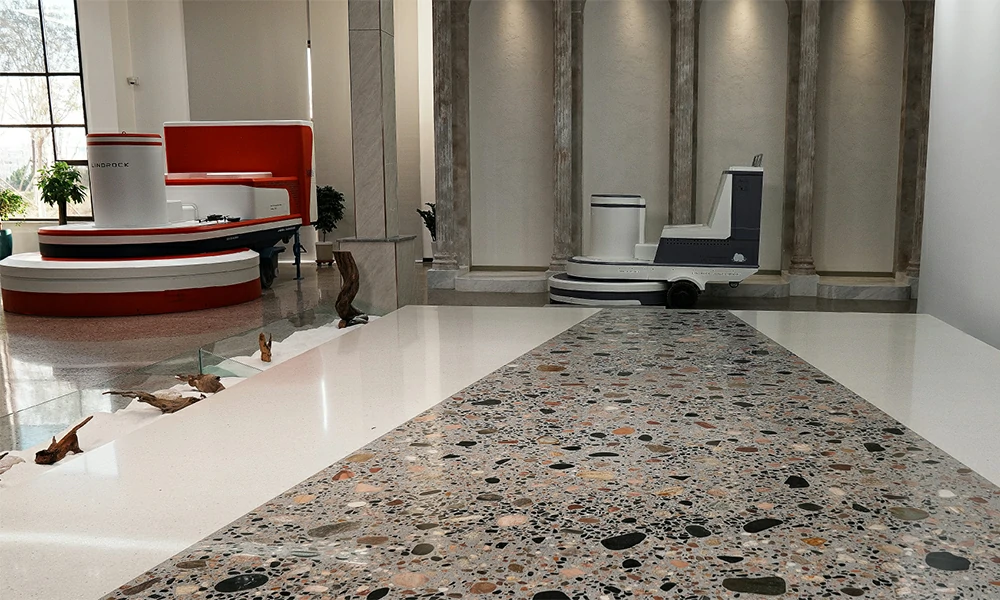
Class-A offices, luxury showrooms, museums, transit hubs, high-end retail - where looks matter and low maintenance is non-negotiable.
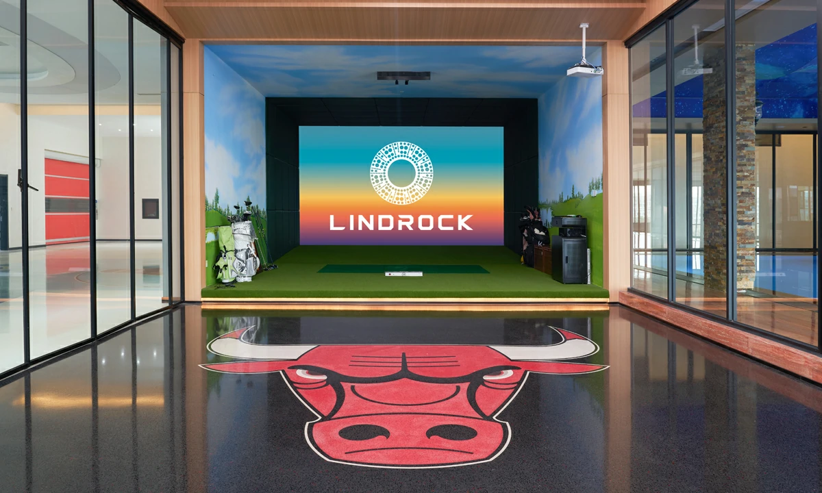
A Three-Tier Grading Standard and Four-Variable Matching System Established for Post-Grinding Floor Flatness
Ultra-Flat Grades
Pre-Construction "3 Checks"
Fully Customizable Finishing Effects
In-Construction "4 Matchings"
| Grade | Standard (Grade 1) | Professional (Grade 2) | Precision (Grade 3) |
|---|---|---|---|
| FF Number | ≥ 75 | ≥ 120 | ≥ 150 |
| FL Number | ≥ 50 | ≥ 80 | ≥ 100 |
| 3m Straightedge | ≤ 3.0 mm | ≤ 2.0 mm | ≤ 1.0 mm |
| Positioning | Suitable for general industrial and commercial floors | Suitable for high-standard commercial and precision manufacturing floors | For ultra-flat warehouses, premium commercial and landmark buildings |
Floor Flatness - Measure flatness to determine grinding pass paths
Floor Hardness - Test hardness to select the appropriate bond matrix
Floor Moisture Content - Test moisture content to prevent blistering
Flatness Grade - Standard / Professional / Precision, determined by FF/FL values · Finalized pre-construction
Aggregate Exposure - Non-exposed / Salt-and-pepper / Medium exposure / Deep exposure, determined by grinding depth · Irreversible process (deep exposure up to 30mm)
Gloss Level - Flat → Matte → Semi-polished → High-gloss → Ultra-gloss, determined by polishing grit count · Adjustable during construction
Bonds & Abrasives - Select abrasives based on floor hardness
Grinding Head Pressure / Machine Weight - Adjust pressure according to floor hardness
Tooling Configuration - Optimize layout to prevent slippage
Travel Speed - Control speed across distinct operational stages
It’s not how fast you grind. It's whether you pass inspection in one go.
Put the same machine on a power-troweled 5,000 psi slab and a soft 2,500 psi pour and you get two completely different jobs. Run the wrong bond and the machine isn’t cutting - it’s just pushing a glazed tool across the floor. Lindrock matches bond, grit, head pressure, and travel speed to the slab before the first pass. That’s when the machine actually delivers its rated production.
| Model | Grinding Width | First-cut Rate |
| LD1800 |
1,800 mm (71 in) |
100–150 m²/hr (1,080–1,615 sq ft/hr) |
| LD1200 |
1,200 mm (47 in) |
80–110 m²/hr (860–1,180 sq ft/hr) |
| LD850 | 850 mm (33 in) | 50–70 m²/hr (540–750 sq ft/hr) |
Watch the dust output. For an LD1800-class machine, while maintaining cut quality, floor flatness, and finish standard, 35 kg (77 lbs) of dust per 10 minutes - roughly 210 kg/hr - is the benchmark for normal cutting speed. Smaller machines produce proportionally less; the principle is the same: watch the dust, not just the speed.
Steady, substantial dust: The tooling is cutting correctly. Diamonds are fracturing and self-sharpening as designed. The bond match is right.
Little or no dust: The tooling has glazed over. Diamonds have gone dull and stopped fracturing. The machine is just riding the surface - speed means nothing.
Sudden heavy dust: On soft concrete, the bond is too hard or the grit too coarse. You’re over-cutting - gouging, swirl marks, and a wavy floor.